Peroxide Cureable Silicone Injection Molding
Ray C. Hetherington, Senior Technical Support, HEXPOL Compounding
Abstract: High Consistency Rubber (HCR) silicone injection molding requires special considerations to manufacture quality parts. The selection of the press, mold design, and gate design are integral to success. HCR silicone processing poses unique challenges when compared with organic polymer based rubber compounds. Part shrinkage, air entrapment, and hot tear issues are examples of processing issues to be considered. Bonding strategies and techniques for metal and plastic substrates are addressed in detail.
Introduction
Maximizing the benefits of High Consistency Rubber (HCR) silicone for injection molding and leveraging its versatility requires special considerations to manufacture quality parts. As with organic polymer compounds, the process for producing parts with HCR silicone includes feeding silicone rubber into the machine’s heated barrel and injecting it into a mold, where it vulcanizes into the designed shape of the part.
Due to its inorganic polymer backbone, HCR silicone processing poses unique challenges when compared to organic polymer-based rubber compounds. This white paper addresses those challenges and how to meet them. Press selection, mold design, and gate design considerations are, in most cases, similar for both HCR silicone and organic rubber. There is commonality between the two. However, processing issues are, in some aspects, significantly different. Therefore, issues such as part shrinkage, air entrapment and hot tear when using HCR silicone are reviewed in detail. Substrate bonding strategies and trouble-shooting steps unique to HCR silicone are addressed as well.
Press Selection
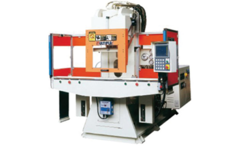
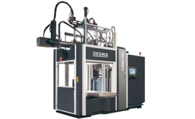
Injection molding machines – also referred to as presses – include two major sections. The injection part of a typical machine includes a barrel, reciprocating screw, and heater. The clamping part of the machine includes a nozzle, mold cavities, molds, and moveable platens. Factors to consider when selecting a press for injection molding, whether using HCR silicone or organic rubber, include:
- Mold Size Requirement
- Tonnage
- Shuttle Requirement
- Vertical or Horizontal Inject ?
- Projected Part Throughput
- Capital Requirement
- Preventative Maintenance
Mold Size Requirement
This basically is ensuring the right size mold and the right size press for the part to be shaped and produced. There are multiple variables to consider when determining the required mold size. First, establish the footprint dimension of the part to be manufactured, as well as the material used to make the part. Because part shrinkage for HCR silicone is typically greater than organic rubber – on average, three and one half percent versus two and one half percent, respectively – different molds might be required. Specific design features of the part are also critical when selecting the required mold size.
Depending on the process, molds have different numbers of cavities and platens. Multiple factors are to be considered depending on the design of the part: will a two-part mold, three-part mold, multi daylight mold be needed? The number of parts to be produced helps determine if a mold with more than two cavities is required.
Molds include cavity and core inserts. The cavity is usually the half of the mold that creates the exterior of the part. The core is the half of the mold that creates the interior, which can house complex components of the part. Platens serve a couple of functions. They provide a place to attach the selected molds and the force necessary to open and close the molds.
Depending on the part to be molded, the design of the mold will require a specific injection point location. Original Equipment Manufacturers (OEMs) make presses with different injection point locations: bottom inject, top inject, or a side inject. The injection point is part specific. The part design determines what injection point location is best suited for the application.
Tonnage
Press tonnage is determined by the size of the desired molded part under clamp. That is, if the mold is too large, it will overhang the machine’s clamping area because the press is too small for that mold. Tonnage is rated by the amount of clamping force the press generates. This force is what keeps the mold closed during the injection of the HCR silicone into the mold. Typically, the larger the molded part, the more tonnage required for the application.
Insufficient tonnage contributes to excess material and part flash and, as a result, increased material variance. This happens when part manufacturers try to squeeze too much out of the existing equipment.
Shuttle Requirement
Shuttle presses increase productivity when properly set up and maintained. They should be considered when the application requires high output manufacturing. Because they feature multiple molds that increase productivity, they are more expensive than other presses and require higher capital expenditures.
Typically, large manufacturing plants have multiple shuttle presses in operation. While one mold is under clamp, in the curing cycle and making a part, the operator has time for opening, flashing, and preparing another mold for the next part. A mold is always under injection, providing quicker turnaround and increased productivity.
Vertical or Horizontal inject?
The vertical injection process is suitable for either insert or non-insert/plastic-metal combined component molding. Vertical presses are best for insert molding because they facilitate positive insert registration alignment. They also save space on the factory floor, with a footprint about half the size of a horizontal press.
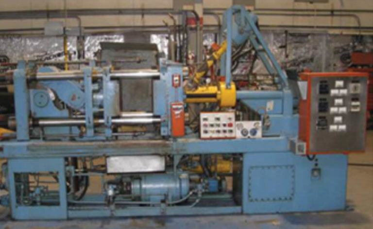
Horizontal injection presses are less common than vertical presses and suitable for non-insert molding. They allow easy removal of molded parts in a variety of ways. One method is to use an automatic brush that descends to remove the part. Horizontal injection presses are more suitable for fully automated production operations. They provide automatic brush cavity cleaning between shots.
Projected Part Throughput
The manufacturer’s stated part-making goal determines the number of presses required. Part throughput should be based on a realistic cure/cycle time so that accurate, realistic production schedules and cost estimates per part can be established. Unrealistic cure/cycle times adversely affect and lower the actual number of parts a press can produce, creating impossible to achieve quality and production goals.
Chemistry limitations drive cure time. Understanding these limitations, per the application, helps ensure accurate cure time estimates. For example, peroxide, which aids the cure process, has a non-negotiable decomposition half-life. Even though different peroxides decompose differently and affect cure time differently, peroxide cannot be pushed beyond the decomposition half-life.
Consider the part size and cross section, i.e., how thick is the part? The heat transfer for the cross section to fully cure is a determining factor of cure time. An extremely aggressive cure time can produce under cured parts, negatively affecting projected part throughput.
Part compression set characteristics affect its performance. The last property to develop in any rubber compound is compression set, which is defined as the deformation that takes place when the elastomer is under strain. The compression set test measures a rubber compound’s complete state of cure. That is the complete cross-linking of the compound.
An auto industry supplier that manufactures hood bumper bolts for trucks illustrates the importance of realistic cure/cycle times. In a recent production run, poor compression set characteristics caused bumper pads to mushroom and split, resulting in rattling hoods on 10,000 new vehicles. After taking a compression set, it was discovered that the cure time was reduced to make more pieces per hour. Labor costs to replace hood bumper bolts for 10,000 vehicles were enormous. Beware of short cuts.
Press Capital Requirement
Larger tonnage presses typically require more capital expense. However, a larger, automated press reduces labor cost and significantly improves productivity. These benefits pay dividends in the long term. Automation enhances operator efficiency, reduces labor costs and human error. If preventative maintenance is practiced, down time is kept to a minimum.
Standardization of press type and manufacturer throughout the plant also reduces capital requirements. Selecting common press components – much like an airline that builds its fleet with the same airplane manufacturer – delivers economies of scale. For example, if a company plans to purchase five presses, it is economically viable to buy them in the same time frame, within the same tonnage range, or at least from the same manufacturer. Benefits include a better purchase price for the presses, common hardware for better maintenance (e.g., hydraulic fittings and hoses) and less downtime, as well as efficient operation. Shops with multiple press types and hardware are more difficult and expensive to manage.
The number of cavities in the mold and the complexity of the part’s design also affect cost. Tolerance requirements and surface finishing are two of the many design variables to be considered.
Whether to buy new equipment versus rebuilt is another consideration. Rebuilt presses are, in some ways, more economical, and the quality is nearly the same as with new machines.
Preventative Maintenance
It is widely known and accepted that preventative maintenance is planned and scheduled to extend equipment life by cleaning, adjusting, repairing and replacing machine parts. In addition to extending machine life, inspecting and correcting potential machine failures before they happen increases up time and productivity.
Not often included in discussions about preventative maintenance is operator safety. Presses running smoothly and in operating order promote accident prevention and are less of a threat to operators.
Machine downtime because of a lack of maintenance means lost productivity and potential harm to operators. Preventative maintenance is critical to a company’s success on multiple levels.
Mold Design Overview
Molds made with hardened steel are very expensive. They last much longer than molds made with low carbon steel, but they are difficult to modify. For example, some molds made in Germany, where they often take six to nine months to build, are typically hardened in every step of the process. They virtually last forever, but the downside is if the mold needs to be modified, or it is damaged, it is difficult and expensive to repair.
Low carbon steel molds are substantially less expensive but wear out considerably faster. They are easier to load and recut and are appropriate for applications requiring the production of hundreds of thousands of parts. If you put inserts where the gates are, when the gates eventually wear out, new inserts eliminate the need recut the gates.
Plating reduces the need for mold release. To guard against mold wear and corrosion, flash chrome plating and electroless nickel are proven coatings. There is also a wide selection of Teflon, diamond-chrome, titanium nitrate and other mold coatings that help keep molds operating for longer periods between repairs. Mold designs and cost-benefit considerations help determine the right coating for the mold and the application.
Mold Design for Insert Molding
Insert molding is a special case with specific issues. Inserts are made of different materials to withstand the silicone injection molding process. Molds used for these applications must have the proper bite shutoff on the insert to prevent flash, meaning that the insert has to be in spec with the mold. If an insert is too thin or worn out, the mold is not going to have enough bite to prevent flash because it’s not contained.
The mold must have vacuum channel to eliminate air entrapment. Similar to a piston and a cylinder in a diesel engine, the entire volume of the silicone rubber part is air until it’s evacuated. If the mold cavity doesn’t have vacuum pull back before injection, an air trap will result. The mold must also have insert support chaplets to prevent parts from moving during injection. This problem is especially apparent with plastic parts and aluminum parts. If the insert is not properly supported in the cavity, the pressure from the injection side of the mold – where it comes into the gate – will shove it to one side or the other.
Mold designs and cost-benefit considerations help determine the right coating for the mold and the application.
Gate Design Overview
There are multiple gate types and sizes used for injection molding. Designed with a small opening, the gate allows the HCR silicone to enter the mold cavity. Gate design, selection, and location are critical to mold quality and productivity. A variety of factors are to be considered when selecting a gate type, such as the size and shape of the part to be molded, mold plates on the press, and economic considerations. The four main gate types addressed here are:
- Cold Runner Gate
- Hot Runner Gate
- Valve Gate
- Fan Gate
Cold Runner Gates
Cold runner gates are more expensive than other types, but they reduce scrap significantly when properly maintained. It’s important to ensure that they never get clogged and that proper coolant flow passes through them. They reduce scrap in two ways. First, they prevent pieces of pre-vulcanized rubber from being injected into subsequent shots. Second, because cold runner gates are automatic and quickly ready for the next shot, there is less material waste.
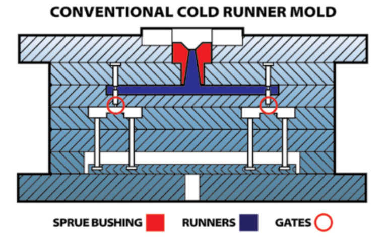
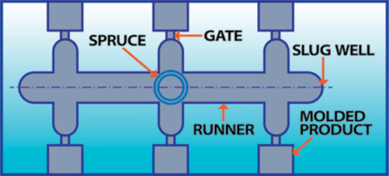
Figure 4 is an example of a conventional cold runner mold. It illustrates how the sprue bushing is at the top of the mold. The material is kept on a runner system as it comes down through the gates. The red circle is essentially a cold block for a cold runner mold.
Hot Runner Gates
Hot runner gates, as shown in Figure 5, are less expensive than cold runner because there is no cooling, but they use more elastomer and produce more unused material. They are often used on low-volume applications and prototype molds because they are so much more economical than the cold runner gate system.
The sprue comes through the center of the mold so that it is balanced, meaning it needs to be symmetrical, otherwise it won’t be the same injection volume. Flow restrictors are used to control shot size to each individual cavity. The gate location in relation to the part impacts the amount of material used and minimizes excess rubber.
A variety of factors are to be considered when selecting a gate type.
Fan Gates
Fan gates (Figure 6) are the least expensive tooling/gate option. Using inserts with fan gates minimizes downtime and, if damaged, they are easier to replace than re-cutting the mold.
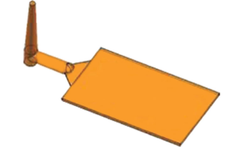
The fan gate is part of the runner system. Typically, it goes into what’s called a tear trim. The sprue can sometimes stick during injection. This recently happened to a multi-million dollar HEXPOL customer that produces rubber bladders. Process difficulties were creating two to three percent scrap because the sprue was breaking off, injecting rubber into the part. Their maintenance department contributed to this problem because they drilled so many times into the sprue bore. To eliminate the scrap, HEXPOL advised them to polish, recut, and polish the sprue bore again, which resulted in near zero scrap.
Valve Gates
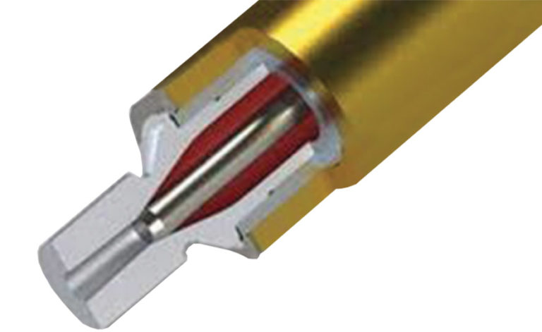
Valve gates minimize runner scrap because a shut-off piston in the valve precisely opens and closes the valve. As shown in Figure 7, the piston comes right down into the part, improving the performance and efficiency of injection molding applications. Valve gates are well suited for automated production because they facilitate faster mold start-ups and cycle times. They deliver excellent ROI by reducing scrap and material variance.
HCR Processing Chemistry
Simply stated, the injection molding process consists of the actual molding of the HCR silicone into a part and the chemistry of the material as it is processed, which in this case is HCR silicone. Injection molding uses a screw plunger to force the silicone into the machine’s mold cavity. The silicone then solidifies and cures to form the designed part. This section of the white paper addresses the chemistry of HCR silicone injection molding and recommended processing.
HCR cure time is determined by the part cross-section thickness, heat transfer, and mold temperature. Keep in mind that the de-composition temperature of the peroxide is the limiting factor in how fast the part can be molded. Higher mold temperatures reduce cure time, but increase hot tear issues (i.e., parts tearing upon removal from the mold). Silicone is the backbone material and, as the temperature increases, a diminishing return results when it starts to tear as it comes out of the mold. Instances of hot tear occur more often with silicone than organic rubber.
The short shot method should be used to determine the proper shot size or volume. A shot is the amount of material required to fill the mold cavity. For initial set-up, the shot size is small, and repeated until the mold is completely filled, which then indicates the size of the shot required for production. This method is recommended because it is not good to overshoot the mold. Too much material will plug up the back end channels.
HCR is Compressible
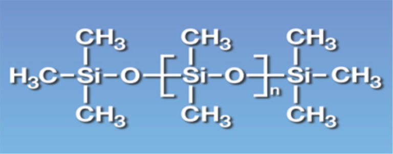
Silicone is somewhat compressible due to the inorganic polymer backbone structure. The silicone/oxygen bond length is much longer and more flexible when compared to organic polymer carbon bond. Figure 8 illustrates the silicone carbon bond backbone structure. This is what gives silicone its broad surface temperature range before breaking down – minus 40° F to +400° F. Organic materials, such as carbon, unless it’s a fluorocarbon, will break down at 250° F degrees.
The surface temperature range resulting from silicone’s flexibility and open interstices is a benefit. But its compressibility during injection contributes to some concerns:
- Over packing of silicone in the mold during part production causes excessive flash and back grinding at the gate. Over injecting pushes the silicone too hard. It’s like a spring and the compressible silicone begins to push back, which is called “suck back at the gate.” This issue is more prevalent with HCR silicone than organic elastomers.
- Compound leakage at the mold sprue bushing is a problem when the process overshoots a mold. The silicone loses viscosity and will flow out of the cavity as the temperature increases, due to over injection. HCR silicone has lower viscosity than organic rubber. A nozzle sprue bushing that is tightly filled helps stop leakage. A protective clamp on the press will minimize damage to the press.
HCR silicone cure system is typically a peroxide. After decomposing to a free-radical attack vinyl at the cure site, it creates a cross-link (vulcanization). A peroxide, such as DBPH-50, is a gas phase curative, and is lost upon opening the mold. It is also confined within the mold, meaning that a post cure to make the part harder is not possible because the cure is gone. It existed in a gas phase only. If the mold is opened too soon upon reducing cure time, it’s gone, forever. Post curing will not work.
For example, an oil pan gasket maker had a production run that was consistently failing leakage tests. After taking the compression set, it was determined the manufacturer didn’t cure the part long enough. All of those parts had to be sorted at the engine plant and thrown away. Not to mention that the engines already assembled with the faulty part had to be retrofitted.
Uncured parts typically cannot be post cured to achieve full properties. Cure time and temperature must allow for full decomposition of the peroxide. Once a mold is opened, because of the DBPH-50 peroxide’s structure (See Figure 9), it dissipates into the atmosphere.
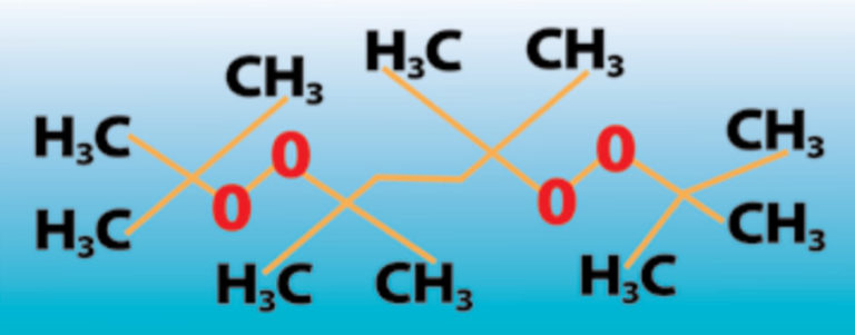
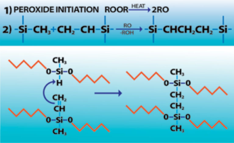
Figure 10 illustrates a VMQ silicone curing reaction. This goes through the heat and creates a free radical. The equation on the left is the vinyl and the hydrogen. When it opens that bond, the peroxide initiates it and forms a carbon/carbon bond, which is very strong and heat stable.
Substrate Bonding Techniques and Strategies
Silicone primers are typically organosilanes. They can be used to enhance bonding between inorganic and organic compounds in a range of coating applications. Organosilanes react with moisture (H2O) to provide cure site attachment to silicone compounds – they hydrolyze the same way car polish turns white (a silanes reaction) just before you wipe it off and it’s converted to a healthy shine. Primers work the same way. Silicone primers can over convert due to extreme humidity and long dwell time causing a bad bond.
To prevent this reaction with moisture, a silicone primer must be stored in a closed container. When the container is left open, it forms a white residue and becomes a crystalline white around the top rim of the container, actually increasing in viscosity. The container should be thrown away.
Primed parts that have been coated more than eight hours prior to molding can be affected by moisture as well, resulting in a suspect bond.
- Aluminum parts require a conversion coating, such as zinc coat plating or iron phosphate, to allow bonding with the primer. Just washing the parts is not sufficient; the bonding will be to aluminum oxide.
- Plastic parts should not contain internal release that will interfere with bonding. A maker of electrical connectors for an automotive application should have been running parts through an electrically heated press. Instead, they were using hydraulic oil and impregnated the material with hydraulic fluid and leaching out, which prevented bonding.
- Grit blasted parts should be washed prior to blasting to prevent oil contamination of blast media. For example, with metal parts, the blast media, whatever you take off of the part, the oil and other residue is sometimes recycled back into the carbon blast, contaminating the part to be bonded.
- Primed parts should be covered prior to molding to prevent airborne surface contamination. It is critical to maintain the cleanest environment possible for parts to be bonded.
Conclusion
High Consistency Rubber (HCR) silicone injection molding requires special considerations to manufacture quality parts. It poses unique challenges compared to organic polymer-based rubber compounds. This white paper addressed some of these challenges, from equipment selection, to processing and chemistry, to substrate bonding strategies.
Some rules of thumb: Proper press selection is always dependent upon the part being molded. Preventative press maintenance is crucial to safety and productivity. HCR silicone must be set up with the proper shot size to prevent over packing.
Press selection, mold design, and gate design considerations are, in most cases, similar for both HCR silicone and organic rubber. There is commonality between the two. However, processing issues are, in some aspects, significantly different.
For example, special attention to part shrinkage, air entrapment and hot tear issues will increase production while minimizing scrap and downtime. Because HCR silicone part shrinkage can be more pronounced than when using organic rubber – on average, three percent versus two percent, respectively – different molds might be required. Hot tear issues are also more prevalent when using HCR silicone, so extra precautions should be taken during the curing stage of injection molding. Proper vacuum is crucial to preventing air entrapment in the mold. Curing the part a little longer than specified helps eliminate imperfections.
Silicone primers can be used to enhance bonding between inorganic and organic compounds in a range of coating applications. Good bonding techniques require attention to detail in both design and process in order to be successful.